
单片机与RA8875接法及软件初始化之二(通过串口连接)
2020-10-22
本篇文章主要介绍使用硬件SPI/IIC以及IO口模拟SPI/IIC方式驱动RA8875
一、硬件设计
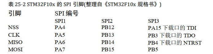
单片机引脚

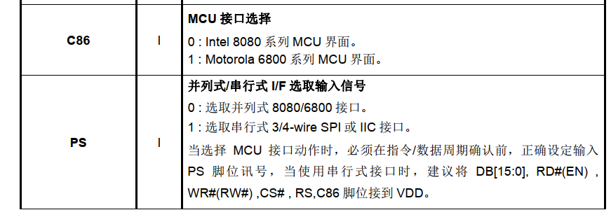
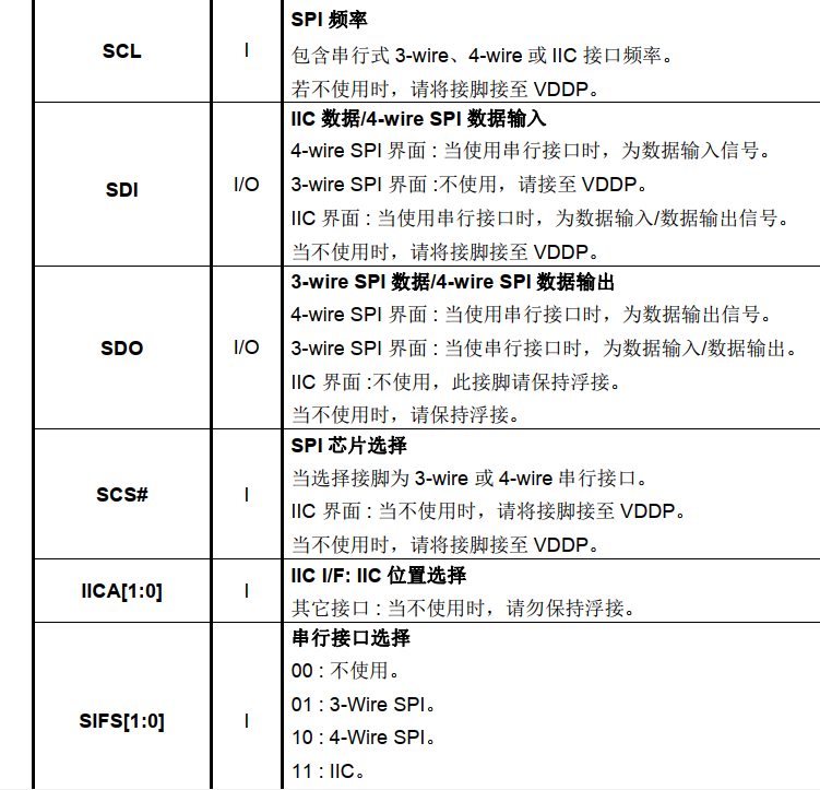
RA8875引脚
二、软件设计
1、硬件SPI //硬件IIC与SPI都属于STM32资源,初始化原理相同这里不做一 一阐述,以SPI为例
初始化
**
static void SPI_Mode_Config(void)
{

  SPI_InitTypeDef  SPI_InitStructure;

RCC_APB2PeriphClockCmd(RCC_APB2Periph_SPI1 ,ENABLE);

SPI_InitStructure.SPI_BaudRatePrescaler = SPI_BaudRatePrescaler_16 ;  //时钟分频因子

//SPI 使用模式3

SPI_InitStructure.SPI_CPHA = SPI_CPHA_2Edge ;

SPI_InitStructure.SPI_CPOL = SPI_CPOL_High ;

SPI_InitStructure.SPI_CRCPolynomial = 7;//不使用CRC功能,数值随便写 //设置CRC校验的表达方式

SPI_InitStructure.SPI_DataSize = SPI_DataSize_8b;

SPI_InitStructure.SPI_Direction = SPI_Direction_2Lines_FullDuplex ;//双线全双工

SPI_InitStructure.SPI_FirstBit = SPI_FirstBit_MSB  ;

SPI_InitStructure.SPI_Mode = SPI_Mode_Master  ;

SPI_InitStructure.SPI_NSS = SPI_NSS_Soft  ;

SPI_Init(FLASH_SPIx,&SPI_InitStructure); //写入配置到寄存器

SPI_Cmd(FLASH_SPIx,ENABLE);//使能SPI

}
写和读函数
**
void LCD_CmdWrite(uint8_t cmd)
{

   Flash_cs_low();

SPI_Peripheral_SendByte(0x80);

SPI_Peripheral_SendByte(cmd);

Flash_cs_high();

}


void LCD_DataWrite(uint8_t Data)

{

    Flash_cs_low();

SPI_Peripheral_SendByte(0x00);

SPI_Peripheral_SendByte(Data);

Flash_cs_high();

}


uint8_t LCD_DataRead(void)

{

   uint8_t Data;


Flash_cs_low();

SPI_Peripheral_SendByte(0x40);

    Data=SPI_Peripheral_ReadByte();

Flash_cs_high();

return Data;

}


uint8_t LCD_StatusRead(void)

{

uint8_t Data;


Flash_cs_low();

SPI_Peripheral_SendByte(0xc0);

    Data=SPI_Peripheral_ReadByte();

Flash_cs_high();

return Data;
**
}
2、普通IO口模拟SPI //3线SPI与4线SPI皆可驱动,3线模式时芯片引脚SDI不适用接至VDD,SDO作为数据传输脚
SPI时序
**
void SPI_Delay(void)
{

unsigned char t;

t=100;    //Adjusted by different

while(--t!=0);

}

void SPI_Init(void)

{

SCK = 1;

SDA = 1;

 ZCS = 1;

}
**
void SPI_Write(unsigned char dat)
{

    unsigned char t = 8;

  do

  {

  SDA = (bit)(dat & 0x80);

  dat <<= 1;

  SCK = 0;

                SPI_Delay();

  SCK = 1;

                SPI_Delay();


  } while ( --t != 0 );

SCK = 1;

SDA = 1;

}
**
unsigned char SPI_Read() //当以4线方式驱动时SDA应改为SDO
{

   unsigned char dat;

   unsigned char t = 8;

 SDA = 1; //SET SDA=1 is let this singal keeping in input mode before read data

 do

 {

  SDA = 1; //SET SDA=1 is let this singal keeping in input mode before read data

  SCK = 0;

  SPI_Delay();

  dat <<= 1;

  if ( SDA ) dat++;

  SCK = 1;

SPI_Delay();

} while ( --t != 0 );

return dat;

}
**
void LCD_CmdWrite(uchar cmd)
{

   SCK = 1;

   SDA = 1;

   ZCS = 0;

   SPI_Delay();

   SPI_Write(0x80);

   SPI_Write(cmd);


   ZCS = 1;


    SPI_Delay();

}
//----------------------//
**
void LCD_DataWrite(uchar Data)

{

   SCK = 1;

   SDA = 1;

   ZCS = 0;

   SPI_Delay();

   SPI_Write(0x00);

   SPI_Write(Data);

   SPI_Delay();

   ZCS = 1;

    SPI_Delay();

}
**
uchar LCD_DataRead(void)
{

   uchar Data;


   SCK = 1;

   SDA = 1;

   ZCS = 0;

   SPI_Write(0x40);

   Data = SPI_Read();

   SPI_Delay();

   ZCS = 1;

return Data;

}
//-----------------------//
**
uchar LCD_StatusRead(void)
{

 uchar Data;


   SCK = 1;

   SDA = 1;

   ZCS = 0;

   SPI_Delay();

   SPI_Write(0xc0);


   Data = SPI_Read();

SPI_Delay();

ZCS = 1;

return Data;

}
初始化芯片及配置相关时钟频率
**
GPIO_ResetBits(GPIOB, GPIO_Pin_7);
    delay_ms(1);

    GPIO_SetBits(GPIOB, GPIO_Pin_7);

    delay_ms(1);


//RA8875_PLL_ini();

LCD_CmdWrite(0x88);

    LCD_DataWrite(0x0b);

    delay_ms(1);

    LCD_CmdWrite(0x89);

    LCD_DataWrite(0x02);

    delay_ms(1);


  LCD_CmdWrite(0x10);  //SYSR   bit[4:3]=00 256 color  bit[2:1]=  00 8bit MPU interface

    //LCD_DataWrite(0x000c);   // if 8bit MCU interface   and 65k color display

   LCD_DataWrite(0x0F); // if 16bit MCU interface   and 65k color display

delay_us(1);


LCD_CmdWrite(0x04);     //PCLK inverse

   LCD_DataWrite(0x81);

delay_ms(1);
液晶屏相关配置 (以AT070TN92为例)
**
//Horizontal set
   LCD_CmdWrite(0x14); //HDWR//Horizontal Display Width Setting Bit[6:0]

   LCD_DataWrite(0x63);//Horizontal display width(pixels) = (HDWR + 1)*8


   LCD_CmdWrite(0x15); //Horizontal Non-Display Period Fine Tuning Option Register (HNDFTR)

   LCD_DataWrite(0x03);//Horizontal Non-Display Period Fine Tuning(HNDFT) [3:0]


   LCD_CmdWrite(0x16); //HNDR//Horizontal Non-Display Period Bit[4:0]

   LCD_DataWrite(0x03);//Horizontal Non-Display Period (pixels) = (HNDR + 1)*8


   LCD_CmdWrite(0x17); //HSTR//HSYNC Start Position[4:0]

   LCD_DataWrite(0x02);//HSYNC Start Position(PCLK) = (HSTR + 1)*8


   LCD_CmdWrite(0x18); //HPWR//HSYNC Polarity ,The period width of HSYNC.

   LCD_DataWrite(0x00);//HSYNC Width [4:0]   HSYNC Pulse width(PCLK) = (HPWR + 1)*8


   //Vertical set

   LCD_CmdWrite(0x19); //VDHR0 //Vertical Display Height Bit [7:0]

   LCD_DataWrite(0xdf);//Vertical pixels = VDHR + 1


   LCD_CmdWrite(0x1a); //VDHR1 //Vertical Display Height Bit [8]

   LCD_DataWrite(0x01);//Vertical pixels = VDHR + 1


   LCD_CmdWrite(0x1b); //VNDR0 //Vertical Non-Display Period Bit [7:0]

   LCD_DataWrite(0x14);//Vertical Non-Display area = (VNDR + 1)


   LCD_CmdWrite(0x1c); //VNDR1 //Vertical Non-Display Period Bit [8]

   LCD_DataWrite(0x00);//Vertical Non-Display area = (VNDR + 1)


   LCD_CmdWrite(0x1d); //VSTR0 //VSYNC Start Position[7:0]

   LCD_DataWrite(0x06);//VSYNC Start Position(PCLK) = (VSTR + 1)


   LCD_CmdWrite(0x1e); //VSTR1 //VSYNC Start Position[8]

   LCD_DataWrite(0x00);//VSYNC Start Position(PCLK) = (VSTR + 1)


   LCD_CmdWrite(0x1f); //VPWR //VSYNC Polarity ,VSYNC Pulse Width[6:0]

   LCD_DataWrite(0x01);//VSYNC Pulse Width(PCLK) = (VPWR + 1)


   LCD_CmdWrite(0xf2);

   LCD_DataWrite(0x01);

//Active window  set

   //setting active window X

    LCD_CmdWrite(0x30); //Horizontal Start Point 0 of Active Window (HSAW0)

    LCD_DataWrite(0x00); //Horizontal Start Point of Active Window [7:0]

//delay_us(1);

    LCD_CmdWrite(0x31); //Horizontal Start Point 1 of Active Window (HSAW1)

    LCD_DataWrite(0x00); //Horizontal Start Point of Active Window [9:8]

//delay_us(1);

    LCD_CmdWrite(0x34); //Horizontal End Point 0 of Active Window (HEAW0)

    LCD_DataWrite(0x1F); //Horizontal End Point of Active Window [7:0]

//delay_us(1);

    LCD_CmdWrite(0x35); //Horizontal End Point 1 of Active Window (HEAW1)

    LCD_DataWrite(0x03); //Horizontal End Point of Active Window [9:8]

//delay_us(1);


   //setting active window Y

    LCD_CmdWrite(0x32); //Vertical Start Point 0 of Active Window (VSAW0)

    LCD_DataWrite(0x00); //Vertical Start Point of Active Window [7:0]

//delay_us(1);

    LCD_CmdWrite(0x33); //Vertical Start Point 1 of Active Window (VSAW1)

    LCD_DataWrite(0x00); //Vertical Start Point of Active Window [8]

//delay_us(1);

    LCD_CmdWrite(0x36); //Vertical End Point of Active Window 0 (VEAW0)

    LCD_DataWrite(0xdf); //Vertical End Point of Active Window [7:0]

//delay_us(1);

    LCD_CmdWrite(0x37); //Vertical End Point of Active Window 1 (VEAW1)

    LCD_DataWrite(0x01); //Vertical End Point of Active Window [8]


// /*setting RA8875 display on*/

    LCD_CmdWrite(0x01); //

    LCD_DataWrite(0x80); //

    delay_ms(20);
至此RA8875初始化完成。
分享到: