
51单片机+RA8875控制液晶显示
2021-01-11
本篇文章分别以AT89C51控制RA8875及RA8876为例,详细讲解8位单片机如何通过瑞佑的液晶控制芯片来进行显示控制。
一、硬件
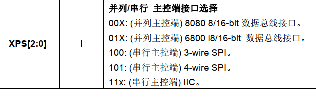
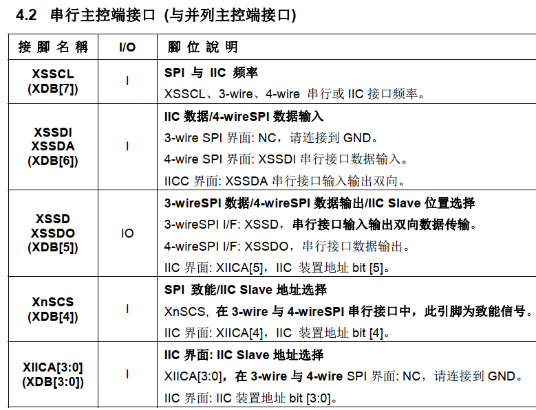
由于8位单片机IO口有限,所以在这里选择SPI通讯方式(还可选择IIC模式)
二、软件
1、软件SPI时序
**
/SPI时序/
void SPI_Init(void)

{

 SCK = 1;

 SDA = 1;

    ZCS = 1;

}


/******************************************************************************

SPI_Write()

******************************************************************************/

void SPI_Write(unsigned char dat)

{

    unsigned char t = 8;

  do

  {

  SDA = (bit)(dat & 0x80);

  dat <<= 1;

  SCK = 0;

                SPI_Delay();

  SCK = 1;

                SPI_Delay();


  } while ( --t != 0 );

    SCK = 1;

    SDA = 1;

}


/******************************************************************************

SPI_Read() If 4-wire SPI be used, and then the SDA singal in this subroutine should be rename to SDO

******************************************************************************/

unsigned char SPI_Read()

{

   unsigned char dat;

   unsigned char t = 8;

 SDO = 1; //SET SDA=1 is let this singal keeping in input mode before read data

 do

 {

  SDO = 1; //SET SDA=1 is let this singal keeping in input mode before read data

  SCK = 0;

  SPI_Delay();

  dat <<= 1;

  if ( SDO ) dat++;

  SCK = 1;

                SPI_Delay();

 } while ( --t != 0 );

 return dat;

}


//*********4_wire_SPI****************************


void LCD_CmdWrite(uchar cmd)

{ uchar j;

   SCK = 1;

   SDA = 1;

   ZCS = 0;

   SPI_Delay();

   SPI_Write(0x80);

   SPI_Write(cmd);

   SPI_Delay();

   ZCS = 1;

}


//----------------------//

void LCD_DataWrite(uchar Data)

{

    SCK = 1;

   SDA = 1;   //

   ZCS = 0;

   SPI_Delay();

   SPI_Write(0x00);

   SPI_Write(Data);

   SPI_Delay();

   ZCS = 1;

}


//----------------------//

uchar LCD_DataRead(void)

{

 uchar Data;

   SCK = 1;

   SDO = 1;   //

   ZCS = 0;

   SPI_Delay();

   SPI_Write(0x40);

   Data = SPI_Read();

   SPI_Delay();

   ZCS = 1;


 return Data;

}

//-----------------------//

uchar LCD_StatusRead(void)

{

 uchar Data;


   SCK = 1;

   SDO = 1;   //

   ZCS = 0;

   SPI_Delay();

   SPI_Write(0xc0);

   Data = SPI_Read();

   SPI_Delay();

   ZCS = 1;

 return Data;

}
2、RA8875芯片时钟频率以及液晶屏参数设置(AT070TN92为例)
**
void INIT(void)
{
RST=0;
delay_us(100);
RST=1;
delay_us(100);
//RA8875_PLL_ini();
LCD_CmdWrite(0x88);
LCD_DataWrite(0x0b);
delay_ms(1);
LCD_CmdWrite(0x89);
LCD_DataWrite(0x02);
delay_ms(1);
LCD_CmdWrite(0x10); //SYSR bit[4:3]=00 256 color bit[2:1]= 00 8bit MPU interface
//LCD_DataWrite(0x000c); // if 8bit MCU interface and 65k color display
LCD_DataWrite(0x0F); // if 16bit MCU interface and 65k color display
delay_us(1);
LCD_CmdWrite(0x04); //PCLK inverse
LCD_DataWrite(0x81);
delay_ms(1);
//Horizontal set
LCD_CmdWrite(0x14); //HDWR//Horizontal Display Width Setting Bit[6:0]
LCD_DataWrite(0x63);//Horizontal display width(pixels) = (HDWR + 1)*8
LCD_CmdWrite(0x15); //Horizontal Non-Display Period Fine Tuning Option Register (HNDFTR)
LCD_DataWrite(0x03);//Horizontal Non-Display Period Fine Tuning(HNDFT) [3:0]
LCD_CmdWrite(0x16); //HNDR//Horizontal Non-Display Period Bit[4:0]
LCD_DataWrite(0x03);//Horizontal Non-Display Period (pixels) = (HNDR + 1)*8
LCD_CmdWrite(0x17); //HSTR//HSYNC Start Position[4:0]
LCD_DataWrite(0x02);//HSYNC Start Position(PCLK) = (HSTR + 1)*8
LCD_CmdWrite(0x18); //HPWR//HSYNC Polarity ,The period width of HSYNC.
LCD_DataWrite(0x00);//HSYNC Width [4:0] HSYNC Pulse width(PCLK) = (HPWR + 1)*8
//Vertical set
LCD_CmdWrite(0x19); //VDHR0 //Vertical Display Height Bit [7:0]
LCD_DataWrite(0xdf);//Vertical pixels = VDHR + 1
LCD_CmdWrite(0x1a); //VDHR1 //Vertical Display Height Bit [8]
LCD_DataWrite(0x01);//Vertical pixels = VDHR + 1
LCD_CmdWrite(0x1b); //VNDR0 //Vertical Non-Display Period Bit [7:0]
LCD_DataWrite(0x14);//Vertical Non-Display area = (VNDR + 1)
LCD_CmdWrite(0x1c); //VNDR1 //Vertical Non-Display Period Bit [8]
LCD_DataWrite(0x00);//Vertical Non-Display area = (VNDR + 1)
LCD_CmdWrite(0x1d); //VSTR0 //VSYNC Start Position[7:0]
LCD_DataWrite(0x06);//VSYNC Start Position(PCLK) = (VSTR + 1)
LCD_CmdWrite(0x1e); //VSTR1 //VSYNC Start Position[8]
LCD_DataWrite(0x00);//VSYNC Start Position(PCLK) = (VSTR + 1)
LCD_CmdWrite(0x1f); //VPWR //VSYNC Polarity ,VSYNC Pulse Width[6:0]
LCD_DataWrite(0x01);//VSYNC Pulse Width(PCLK) = (VPWR + 1)
LCD_CmdWrite(0xf2);
LCD_DataWrite(0x01);
//Active window set
//setting active window X
LCD_CmdWrite(0x30); //Horizontal Start Point 0 of Active Window (HSAW0)
LCD_DataWrite(0x00); //Horizontal Start Point of Active Window [7:0]
//delay_us(1);
LCD_CmdWrite(0x31); //Horizontal Start Point 1 of Active Window (HSAW1)
LCD_DataWrite(0x00); //Horizontal Start Point of Active Window [9:8]
//delay_us(1);
LCD_CmdWrite(0x34); //Horizontal End Point 0 of Active Window (HEAW0)
LCD_DataWrite(0x1F); //Horizontal End Point of Active Window [7:0]
//delay_us(1);
LCD_CmdWrite(0x35); //Horizontal End Point 1 of Active Window (HEAW1)
LCD_DataWrite(0x03); //Horizontal End Point of Active Window [9:8]
//delay_us(1);
//setting active window Y
LCD_CmdWrite(0x32); //Vertical Start Point 0 of Active Window (VSAW0)
LCD_DataWrite(0x00); //Vertical Start Point of Active Window [7:0]
//delay_us(1);
LCD_CmdWrite(0x33); //Vertical Start Point 1 of Active Window (VSAW1)
LCD_DataWrite(0x00); //Vertical Start Point of Active Window [8]
//delay_us(1);
LCD_CmdWrite(0x36); //Vertical End Point of Active Window 0 (VEAW0)
LCD_DataWrite(0xdf); //Vertical End Point of Active Window [7:0]
//delay_us(1);
LCD_CmdWrite(0x37); //Vertical End Point of Active Window 1 (VEAW1)
LCD_DataWrite(0x01); //Vertical End Point of Active Window [8]
// /*setting RA8875 display on*/
LCD_CmdWrite(0x01); //
LCD_DataWrite(0x80); //
delay_ms(20);
/*setting RA8875 memory clear with active window*/
Clear_Active_Window();
// /*setting backlight on RA8875 PWM1 control*/
// PWM1_enable();
// PWM1_fnuction_sel();
// PWM1_clock_ratio(0x02); //bit0~3 58KHZ
// PWM1_duty_cycle(0xff); // 獹
// Brightness_level=10;
//LCD_Clear(0xffff);//
Text_color(0xFFFF);
Geometric_Coordinate(0,800,0,480);
Draw_square_fill();
Chk_Busy();
}3、RA8876芯片及液晶屏初始化函数调用(RA8876_Initial(); )
**
**RA8876_Initial
{**

RA8876_HW_Reset();
Check_IC_ready();

// System_Check_Temp();


RA8876_SW_Reset();

Check_IC_ready();


//------------------------------------

RA8876_PLL();// Set RA8876/77 PLL and Start PLL.

//------------------------------------

RA8876_SDRAM_initial();// set the SDRAM parameter.

//------------------------------------


//**[01h]**//

TFT_24bit();//RA8876 only


//**[01h]**//

#if defined (MCU_8bit_ColorDepth_8bpp) || defined (MCU_8bit_ColorDepth_16bpp) || defined (MCU_8bit_ColorDepth_24bpp)

Host_Bus_8bit();

#endif


#if defined (MCU_16bit_ColorDepth_16bpp) || defined (MCU_16bit_ColorDepth_24bpp_Mode_1) || defined (MCU_16bit_ColorDepth_24bpp_Mode_2)

Host_Bus_16bit();

#endif

//**[02h]**//

Data_Format_8b_16bpp();

MemWrite_Left_Right_Top_Down();//(Default) Memory Write: Left to Right, Top to Down.

//------------------------------------

//**[03h]**//


Graphic_Mode();

// Text_Mode();


Memory_Select_SDRAM();


//------------------------------------

//** Set color depth, define in [UserDef.h] **//

Select_Main_Window_16bpp(); //[10h]Set main window color depth

Memory_16bpp_Mode(); //[5Eh]Set active memory color depth


Select_PIP1_Window_16bpp(); //[11h] PIP 1 Window Color Depth

Select_PIP2_Window_16bpp(); //[11h] PIP 2 Window Color Depth


BTE_S0_Color_16bpp(); //[92h] Source_0 Color Depth

BTE_S1_Color_16bpp(); //[92h] Source_1 Color Depth

BTE_Destination_Color_16bpp(); //[92h] Destination Color Depth

//**[12h]~[1Fh]]**//

Set_LCD_Panel(); // define in [UserDef.h]


//------------------------------------

//**[20h][21h][22h][23h]**//

Main_Image_Start_Address(0);

//**[24h][25h]**//

Main_Image_Width(2048);

//**[26h][27h][28h][29h]**//

Main_Window_Start_XY(0,0);

//**[50h][51h][52h][53h]**//

Canvas_Image_Start_address(0);

//**[54h][55h]**//

Canvas_image_width(2048);

//**[56h][57h][58h][59h]**//

Active_Window_XY(0,0);

//**[5Ah][5Bh][5Ch][5Dh]**//

Active_Window_WH(1024,600);

BTE_Solid_Fill(0,2048,0,0,0x0000,1024,600); //Memory Clear

}
三、相关API函数的调用
RA8875函数库:“RA8875_subroutine.c”,“lcd.c”
RA8876函数库:“RA8876.c”,“RA8876_API.c”,“RA8876_MCU_IF.c”
瑞佑芯片有非常完善方便调用的函数库,由于C51存储空间较小,建议将需要用到的函数从函数库中复制出来调用。
DEMO展示:
**
Text_color(Red); //RA8875
Geometric_Coordinate(10,200,10,10);

Draw_line();

Chk_Busy();

RA8875_Draw_Circle_Square(50,50,200,200,Red);

Draw_Triangle_3point_Coordinate(10,20,80,90,80,20);

Draw_Triangle();


Draw_Triangle_3point_Coordinate(400,20,600,200,600,20);

Draw_Triangle_fill();


Circle_Coordinate_Radius(100,250,50);

Draw_circle_fill();

  Chk_Busy();


Text_color(Red);

Circle_Square_Coordinate_setting(300,400,0,100,10,10);

Draw_Circle_Square_fill();

Chk_Busy();
分享到: